Automatic Watering System With A Raspberry Pi
By jason2605 on Sat Apr 10 2021
If you're anything like me then I feel sorry for your plants, you buy them with great intention of keeping good care of them, then suddenly a week has gone by and you have forgotten to water them... Rather than taking the sensible option and just, you know, watering them, I decided that this would be a fun project for my Raspberry Pi that has recently been collecting dust. To spice things up a little bit I decided to challenge myself to write all of the code required to build this in Dictu. For those not in the know, Dictu is a programming language created by yours truly. Before I started with the project, I had a few requirements that I wanted to meet for this to be considered a successful project by myself:
- For it to actually work correctly...
- For all (if not most) of the code to be written in Dictu
- For it to only water when soil levels reach a certain "dryness" rather than on a schedule
- For it to monitor water levels and notify me when they are low
- Everything to be encased in a semi-presentable format
GPIO
Before setting off and ordering a load of parts for the Raspberry Pi, I wanted to make sure that I could actually work with the RPi GPIO pins via Dictu, which involved creating a GPIO library of sorts. This (luckily) turned out to be a lot simpler than I had first thought, it boils down to reading and writing to files depending on the desired action. With help from already written things, such as this node library and this shell snippet, I managed to create a very simple library that deals with exactly what I want. Before I get into the Dictu library, I thought it's best to explain a little about how the GPIO pins are controlled via the filesystem - if you're not interested in this part, feel free to skip to the next section.
All GPIO files are located within the /sys/class/gpio directory, in here is where we can export and unexport pins. export-ing a pin is essentially "activating" a pin on the RPi board, and this needs to be done before we can do anything with the pin. You export a pin by writing a pin number to the export file (note pin numbers here are BCM numbers and not physical pin numbers). Once the pin has been exported it will create a new directory with the name gpio<num> where <num> is the pin number which has just been exported along with other files within the new directory. For example, if we export pin 17 then it will create a new directory gpio17 with the following structure:
gpio17
-- active_low
+-- device -> ../../../gpiochip0
+-- direction
+-- edge
+-- power
| +-- autosuspend_delay_ms
| +-- control
| +-- runtime_active_time
| +-- runtime_status
| \\-- runtime_suspended_time
+-- subsystem -> ../../../../../../../class/gpio
+-- uevent
\\-- value
After exporting a pin we next need to set its direction, since pins can be used for both input and output we need to tell the pin which it is we want to do, so for example, if we want to read data from a sensor we need to set the direction of the pin to in however, if we want the pin to act as a power output, e.g to power an LED, we need to set the direction to out. This is simply done by writing either in or out to the direction file. The next file we need to use is value. Similar to direction, how we interact with it is based upon whether our pin has been setup for reading or writing (in or out). If our pin is in an input state then we will read the value file, and based on the input from the external circuit, it will either read 1 (high) or 0 (low). Similarly, if we are in an output state, we use 1 (high) and 0 (low) however, we write these values to the value file instead of reading. There are obviously other files within the gpio17 directory, but they were unnecessary for this project. Finally, once you are done with the pin we need to unexport it to clean the pin up. Just like exporting you write the pin number to the unexport file.
Dictu GPIO
import Path;

class GPIO {
    var PATH = "/sys/class/gpio";
    var ACTIVE_PINS = {};

    /**
    * pin: BCM pin number
    * direction: in or out
    */
    static setup(pin, direction) {
        if (pin < 0 or pin > 40) {
            return Error("Invalid pin number, must be between 0-40");
        }

        pin = pin.toString();

        if (!["in", "out"].contains(direction)) {
            return Error("Pin direction must be in or out");
        }

        var pinObject = Pin(pin, direction);
        GPIO.ACTIVE_PINS[pin] = pinObject;

        return Success(pinObject);
    }

    cleanAll() {
        GPIO.ACTIVE_PINS.keys().forEach(def (key) => {
            const pin = GPIO.ACTIVE_PINS[key];
            pin.cleanup();
        });
    }
}

class Pin {
    var PATH = "/sys/class/gpio";

    init(private pin, private direction) {
        this.unExport();
        this.export();

        while (!System.access("{}/gpio{}/value".format(Pin.PATH, this.pin), System.R_OK | System.W_OK).success()) {
            System.sleep(0.01);
        }

        this.setDirection();
    }

    read() {
        var content = "";

        with("{}/gpio{}/value".format(Pin.PATH, this.pin), "r") {
            content = file.read().strip();
        }

        return content;
    }

    write(value) {
        const allowedValues = {
            true: "1",
            false: "0"
        };

        const writeValue = allowedValues.get(value, nil);

        if (writeValue == nil) {
            return Error("Invalid write value");
        }

        with("{}/gpio{}/value".format(Pin.PATH, this.pin), "w") {
            file.write(writeValue);
        }

        return Success(nil);
    }

    cleanup() {
        this.unExport();
    }

    private export() {
        if (!Path.exists("{}/gpio{}".format(Pin.PATH, this.pin))) {
            with("{}/export".format(Pin.PATH), "w") {
                file.write(this.pin);
            }
        }
    }

    private unExport() {
        if (Path.exists("{}/gpio{}".format(Pin.PATH, this.pin))) {
            with("{}/unexport".format(Pin.PATH), "w") {
                file.write(this.pin);
            }
        }
    }

    private setDirection() {
        with("{}/gpio{}/direction".format(Pin.PATH, this.pin), "w") {
            file.write(this.direction);
        }
    }
}
This is essentially the entire GPIO library used, written in Dictu. There could definitely be improvements made to it, however, I kept it incredibly simple for this project. Once I had this written I tested it using a breadboard along with an LDR (Light Dependent Resistor) I had lying around, and it worked great!
Parts
Once I had a functioning GPIO library I was happy to get my wallet out and order the parts required to create this. I used The Pi Hut to order my parts and they were great (no this isn't a sponsored post).
Parts List
- Immersible Pump & WaterTube
- Soil Moisture Sensor
- Relay
- Ultrasonic Distance Sensor
- Ultimate Resistor Kit
- 12V Power Supply
- Power Switch
Total: £43.49
Most of the parts in the list are fairly self-explanatory however I will explain about a couple of the parts in a little more depth.
Ultrasonic Sensor
The ultrasonic sensor is effectively two speakers and a receiver, it pumps out a sound wave which bounces off an object and is caught by the receiver. This is useful to us because we can time how long it takes for the sound wave to bounce and come back and work out how far its travelled - this means we can work out whether or not we need to fill the "tank" up with water.
More Detail
Sound waves travel at 343m/s at sea level through air and if you remember back to your days of Physics lessons you may remember that speed = distance / time. We know the speed the sound wave is travelling, we are monitoring how long it takes and we are attempting to find the distance the sound wave has travelled, so with a bit of rearranging we end up with distance = speed * time. We however are not done there, this would give us the total distance travelled by the sound wave, which is 2 times to big (since it's hitting the water container and bouncing back), so we end up with distance = speed * time / 2.
Relay
A relay is a fancy electronically operated switch. We need a relay here since our pump is working on 12V and the RPi works at 3.3V (also 5V pins), this means we will need a completely separate circuit setup, however it still needs to be controllable by the Pi.
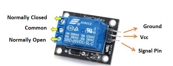
A relay works by using an electromagnet to either open or close a circuit depending upon whether or not a voltage is being supplied to the signal pin and how the circuit is setup on the opposite side of the relay. If the circuit is setup via "Common" and "Normally Closed" this means the circuit is closed (not active) when there is no current being passed to the signal pin, however if it was setup so that it uses "Common" and "Normally Open" the circuit would default to open (active) when there is no current being passed to the signal pin. In our case we only ever want the pump to be active when we turn on the GPIO pin (signal pin) so in this scenario the "Normally Closed" option is chosen.
Case
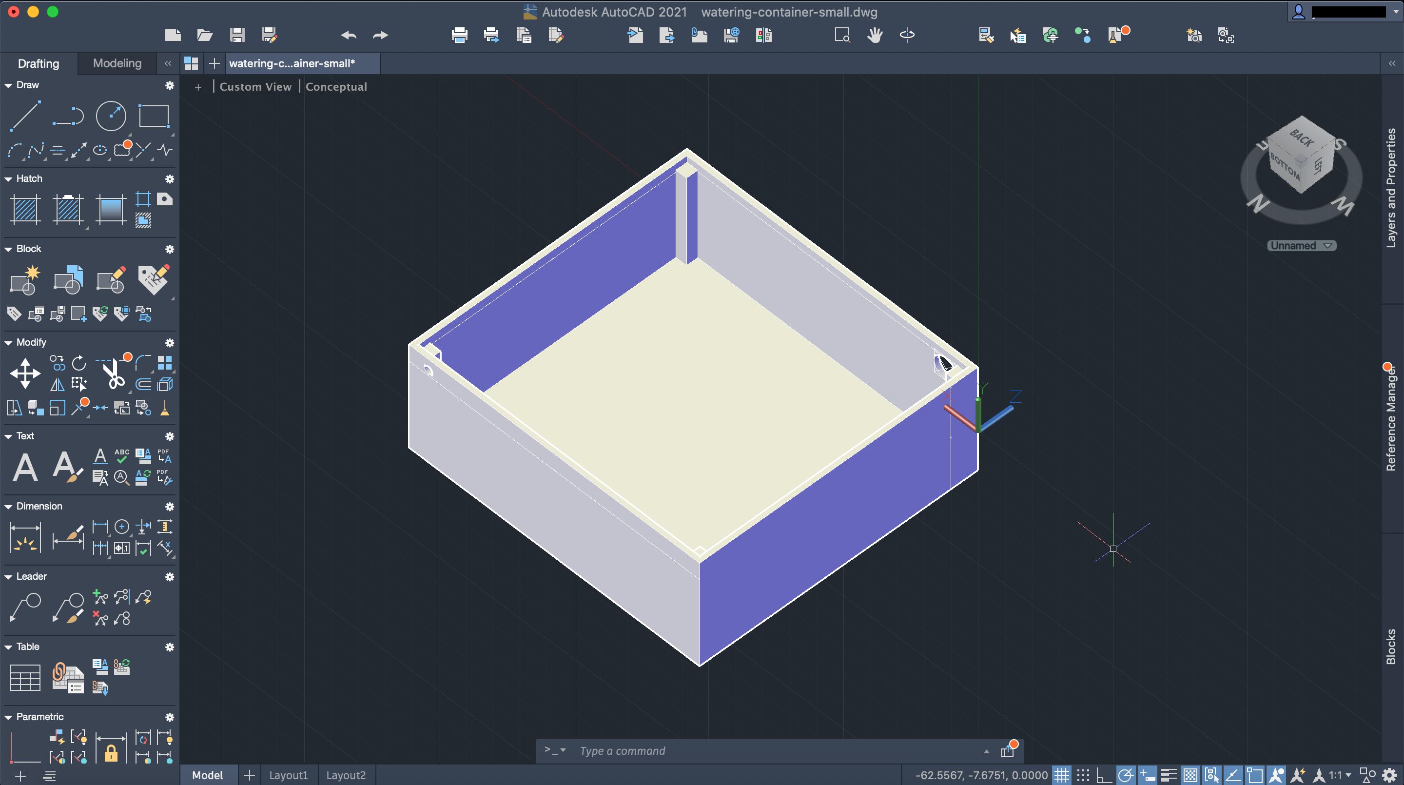
One of my requirements is that it is in a presentable format, in theory I will be using this system on 3 bonsai trees that I have growing and ideally I don't want an absolute mess around the trees, since you know, you don't want to have to gouge your eyes out. To do this I created my own case with a 3D printer. It is essentially in 3 different parts, the water container at the bottom holding the submersible pump and obviously water, the middle section which holds the Raspberry Pi and related electronics and then finally the lid. To design the different sections I used AutoCAD, which luckily for me, provides free access to students (again not a plug), otherwise you're looking at thousands for a license - which isn't really what I was looking to pay for a hobby experiment. Anyways... after a lot of pretending to measure things, and some trial and error, I ended up with these 3 designs:
Water Container
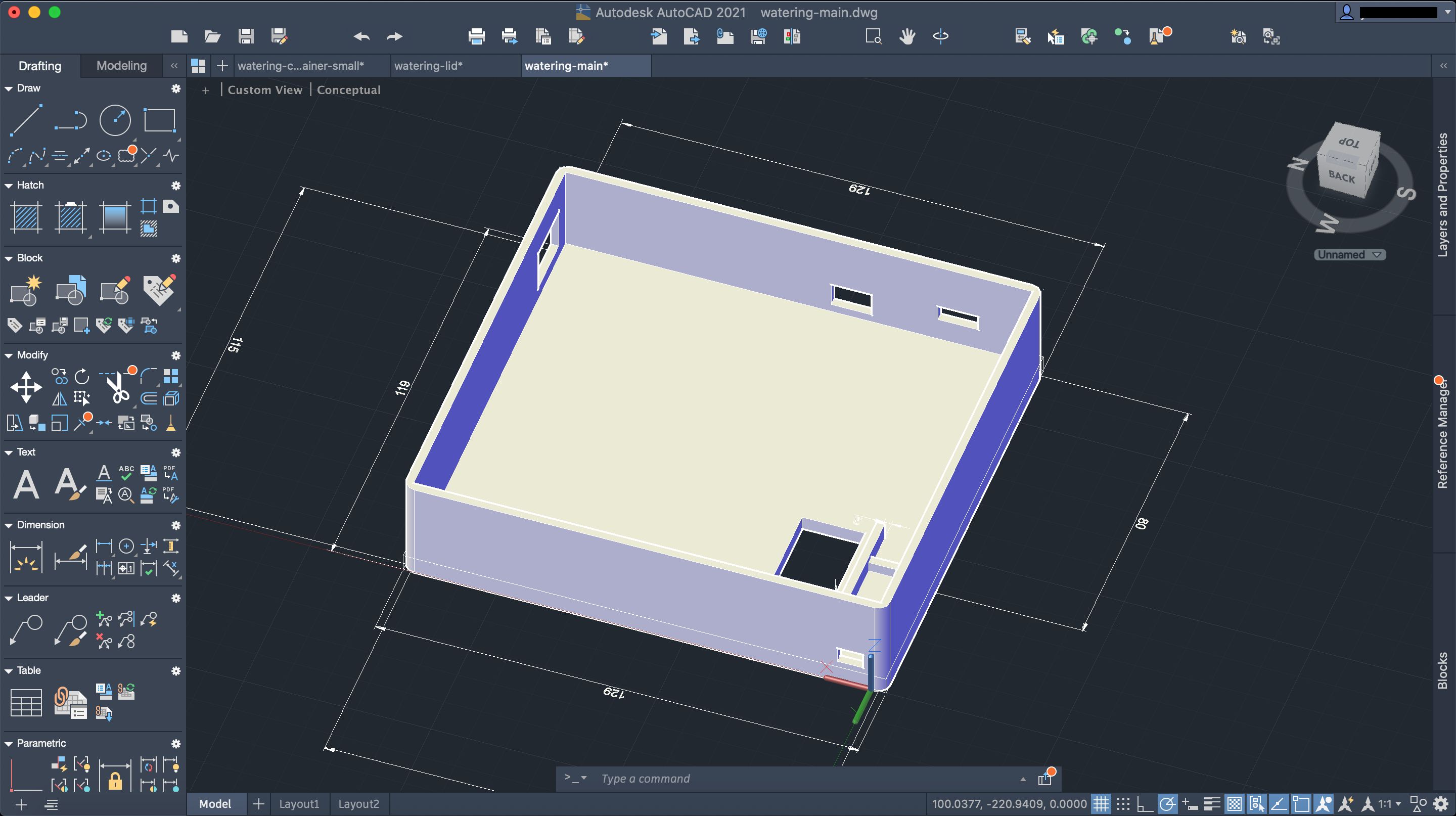
Main Section
Lid
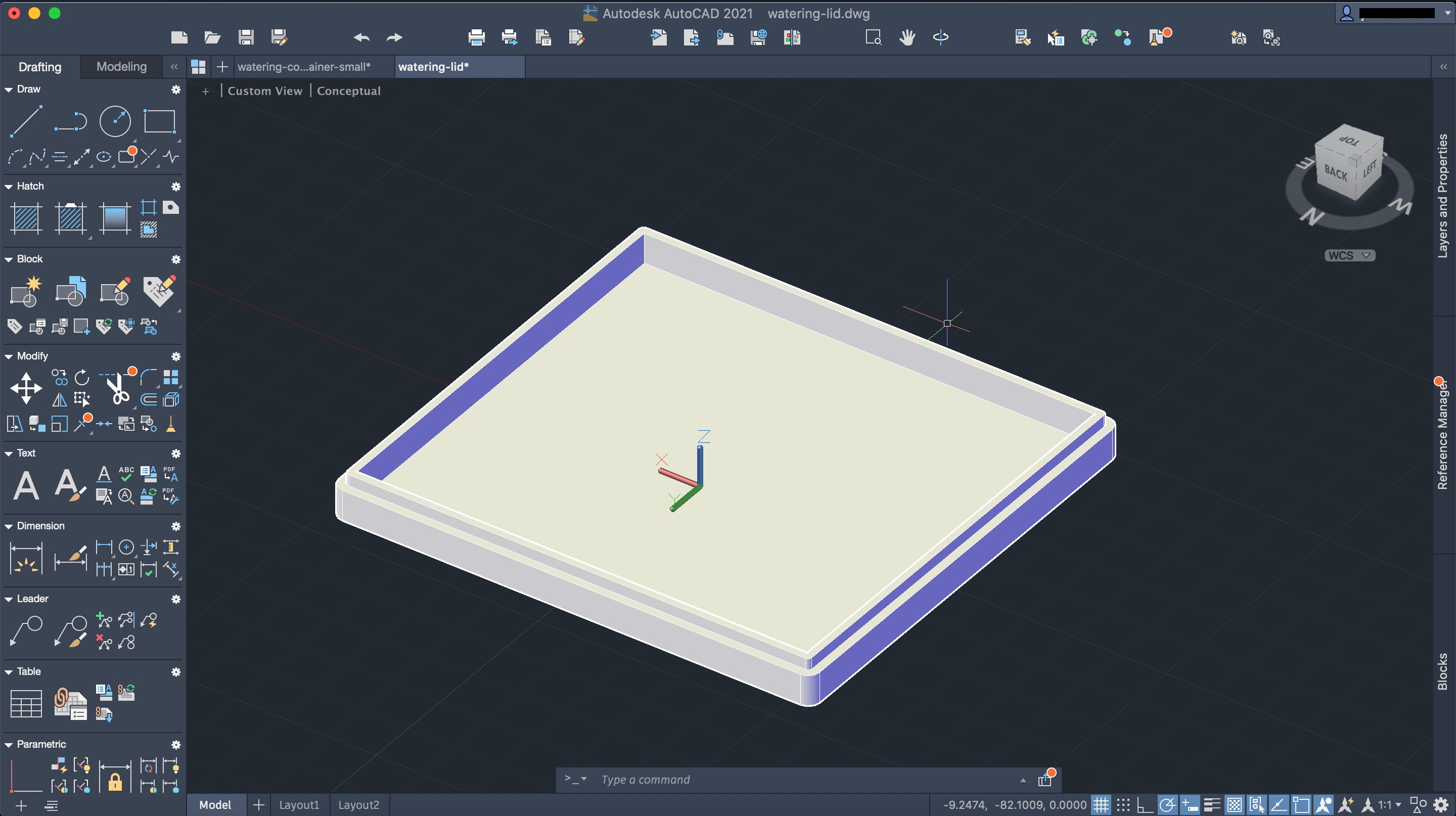
And then it was finally time to print!
Printing
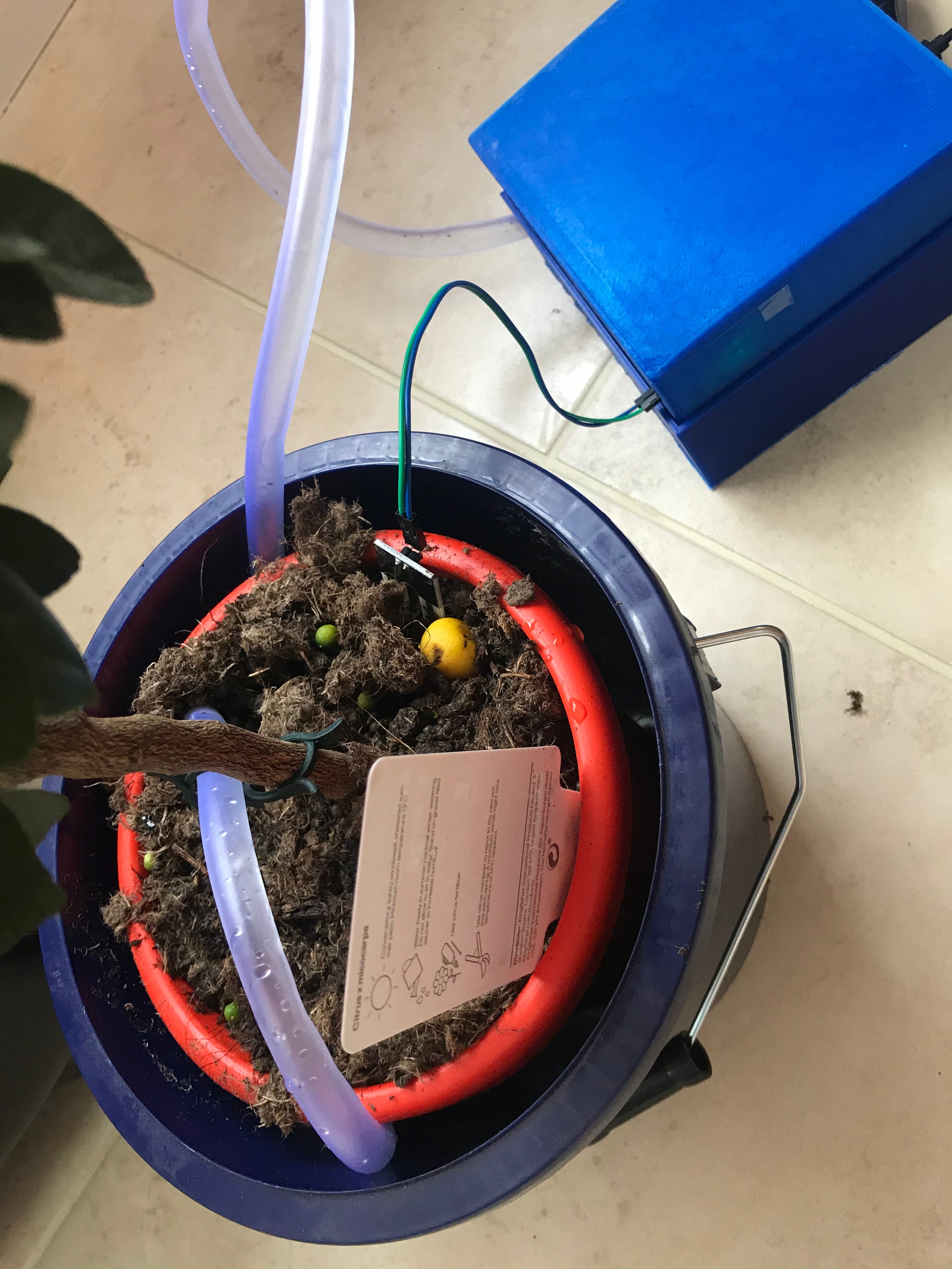
A couple of failed attempts and a few days, I eventually reached a stage where I could begin placing components within the printed design!
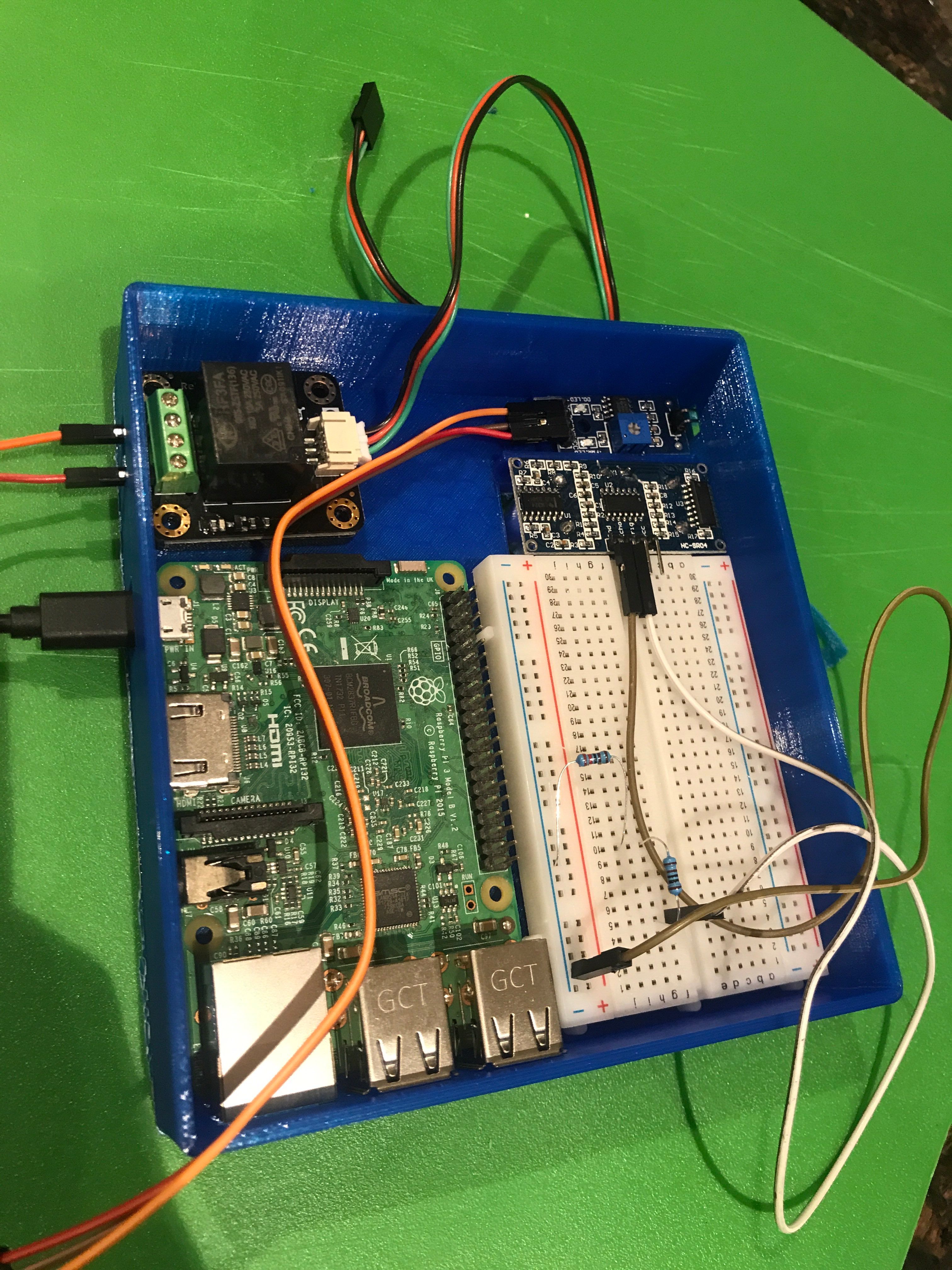
Note: I did cheat here and use a breadboard and jumper cables, sorry.
Writing The Project Code
I was now at a stage where I had a proof-of-concept GPIO library written, and a container for the electronics; it was finally time to write the actual project code and finish this!
Getting Soil Moisture Level
The first thing tackled was hooking up the soil moisture level sensor. Since the Raspberry Pi deals with digital inputs, this sensor will give off either a high reading or a low reading depending upon whether or not the soil is dry (configurable via a potentiometer).
/**
 * Get the soil moisture level.
 * - 1 means the level is dry
 * - 0 means the level is wet
 */
def getSoilLevel() {
    const pin = gpio.setup(17, "in").unwrap();
    const level = pin.read();
    pin.cleanup();
    return level;
}
The above code is hopefully fairly self-explanatory, we essentially get input from the sensor which is either "dry" or "wet".
Measuring The Water Level
The main container sits atop of the water container, this allows us to measure the distance of a sound wave from the main section to the bottom of the water container telling us how much water is left in the container. The slight caveat here is that sound actually travels much faster in water than it does in air, which means it slightly throws off the distance measurement since we are using the constant at which it travels in air (343m/s). This in theory however should not make a difference, because it will give us a lower reading rather than higher, so we can just cater for this.
/**
 * Get the amount of water in the container.
 * Printed container is ~3.7cm deep, this means if we hit 3 centimeters
 * it needs refilling.
 */
def getWaterLevel() {
    const trigPin = gpio.setup(23, "out").unwrap();
    const echoPin = gpio.setup(24, "in").unwrap();

    trigPin.write(false).unwrap();

    // Settle sensor after reset
    System.sleep(2);
    trigPin.write(true);
    System.sleep(0.00001);
    trigPin.write(false);

    var pulseStart = System.time();

    while (echoPin.read() == "0" and System.time() - pulseStart < 5) {}

    var start = System.time();

    pulseStart = System.time();

    while (echoPin.read() == "1" and System.time() - pulseStart < 5) {}

    var end = System.time();
    const pulseDuration = end - start;

    /**
    * Speed of sound at sea level is 343m/s
    * Formula is speed = distance / time, however our formula is
    * speed = distance / (time / 2), since we only care about the speed
    * from the distance of the sensor to the object (not back again).
    *
    * 34300 = distance / (time / 2)
    * 17150 = distance / time
    * distance = 17150 * time
    *
    * Note: Speed of sound in water is faster, but that doesn't matter
    * much in this case since it'll reduce the "distance", and we're
    * checking for an empty container.
    */

    const distance = pulseDuration * 17150;

    trigPin.cleanup();
    echoPin.cleanup();

    return distance;
}
Activating The Pump
Once we receive the signal that the soil is dry and the container is not empty, we then want to turn on the pump.
/**
 * Activate the water pump
 */
def runPump() {
    const pin = gpio.setup(18, "out").unwrap();

    print("Running Pump!!!");
    // Turn pump on
    pin.write(true).unwrap();

    const startTime = System.time();
    // Wait until the sensor measures wet soil OR 5 seconds has passed
    while (getSoilLevel() == "1" and System.time() - startTime < 5) {
        System.sleep(0.1);
    }
    // Turn pump off
    pin.write(false).unwrap();
    pin.cleanup();
}
The script will run until the soil is wet OR until 5 seconds has passed. The 5 seconds is more of a failsafe incase anything goes wrong with the sensor and the pump is never switched off.
Running
/**
 * Entrypoint
 */
def monitor() {
    const waterLevel = getWaterLevel();
    print("Water level {}".format(waterLevel));
    // Water is empty
    if (waterLevel >= 3.7) {
        print("Water empty!!");
        return;
    }
    // Water is getting low
    if (waterLevel >= 3) {
        sendNotification();
    }
    const soilLevel = getSoilLevel();
    print("Soil level {}".format(soilLevel));
    if (soilLevel == "1") {
        runPump();
    }
}
Putting this all together we have our entry point, our "main" function if you will. The water container printed currently can has a depth of around 3.7cm, so we send a notification when we have around 3cm of distance because at this point the water level is getting low. The notification sent is an SMS message via Twilio SMS API.
Round Up
This was a really interesting project to make, I'm sure there are things that can be improved, or additional things that could be added however I'm currently at a stage where I'm happy with the project. Looking back I managed to hit those 5 requirements I'd set out to meet which, honestly, is not what I was expecting.